Old Iron
Well-known member
Right on looks great
[P[P[P
[P[P[P

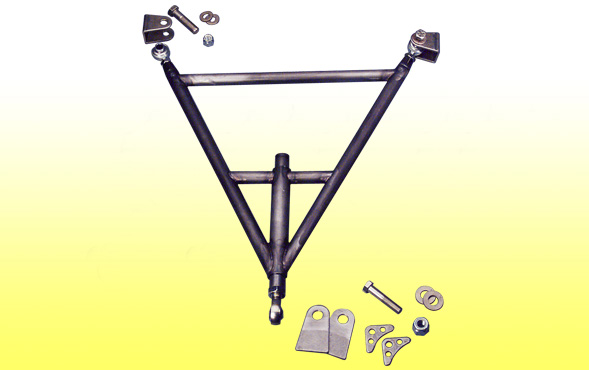
You're not wrong on the shock application.
The only difference that I do is not weld the bolt on the shock side due to the fact it can cause the bolt to have a tendency to crack from the heat. When you tighten the shock sleeve against the tubing then that's enough to work.
Thanks Bob....so only plug weld the back side? Just making sure I understand.
Yes, it makes a stronger setup
 )
)
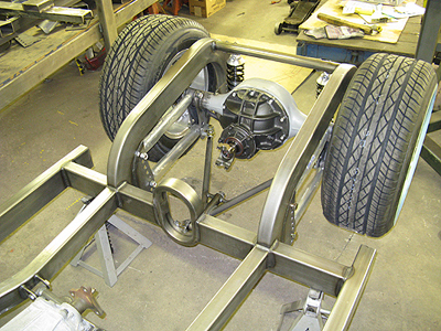
I'm thinking that the diff mounted end is not going to be strong enough, All the side loads when turning (doing donuts) are on the panhard bar. The center of the bar is a long way up supported only by the flat plates of the 4 link and the bar extention. I would try to triangulate it.
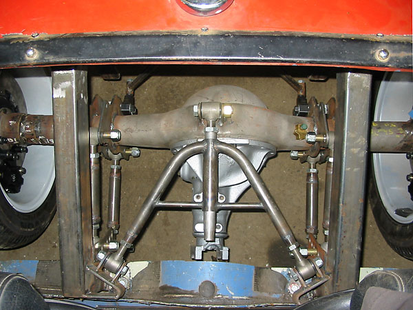
Best to have the pan hard bar level with the ground at ride height so the bracket that is on the frame needs to be low enough to make the bar level with the ground. The pan hard has an arch that it travels through and at the same time slightly moves the rear end to the side that is anchored to the frame. The longer the bar the less the rear moves off center.
If you had a mind to you can use what is called a wishbone pan hard that keeps the rear end centered at all times. It mount to the rear end and a bracket on the cross member of the frame in front of the rear end. This style does not need to be level with the ground as the front heim is on a slide bar that moves in and out as needed. This bar can also be mounted with the yoke forward to the frame or back on the rear end housing and above or below the drive shaft.
Enter your email address to join:


