My 1941 Dodge Truck Build

Rat Rods Rule

Help Support Rat Rods Rule:

This site may earn a commission from merchant affiliate links, including eBay, Amazon, and others.
A little update:

I was a trooper and stayed in the heat to get the transmission crossmember done. Well, it is done and welded in the frame. I just need to finish welding it to the frame on the underside, because it was late and I didn't feel like jacking up the frame to get under it.

I welded the frame tubes up.
IMG_0308.jpg


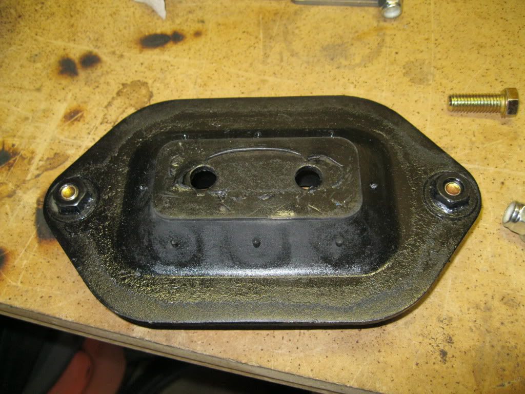
My Cadillac THM400 mount finally came in. It's totally different from a Chevy THM400 if you're wondering.
IMG_0303.jpg


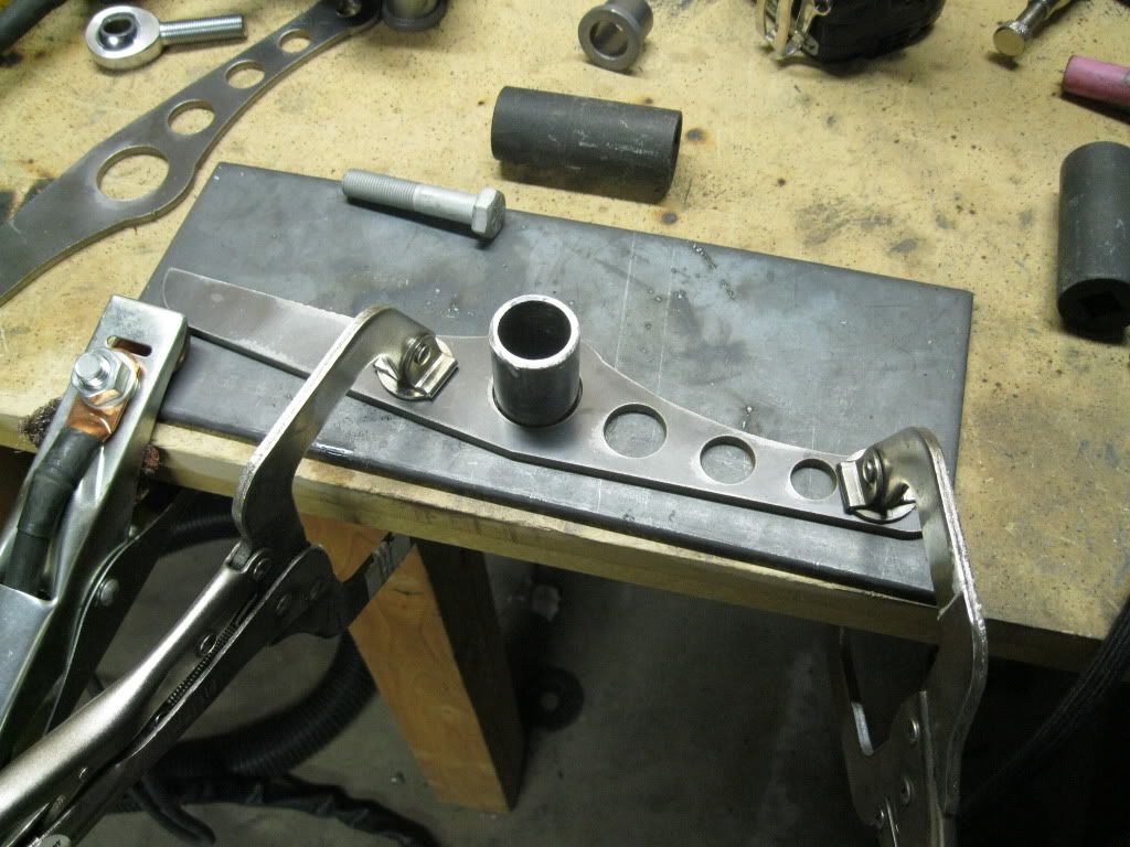
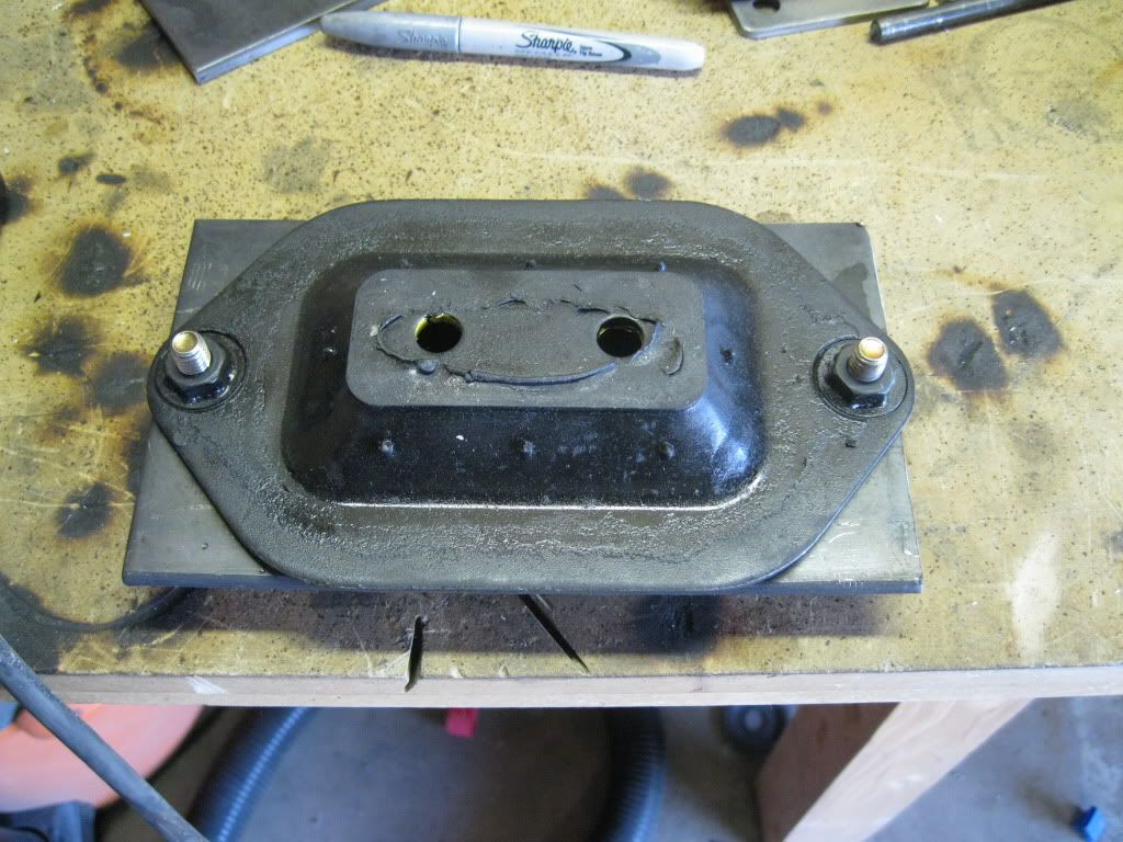
I cut a section out of the middle of a 1/4" plate and drilled it to mount the mount to.
IMG_0305.jpg


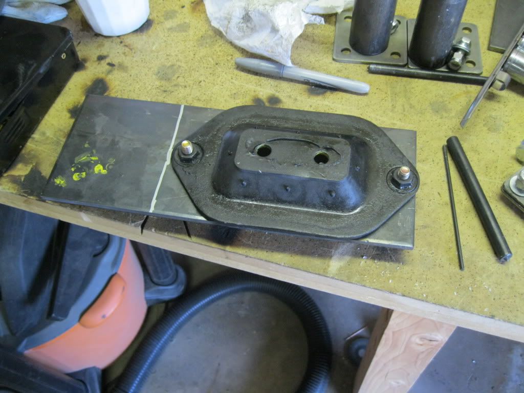
I trimmed the plate.
IMG_0307.jpg


I forgot taking pictures of a couple steps. A few steps are going to be shown in one picture. So sorry!

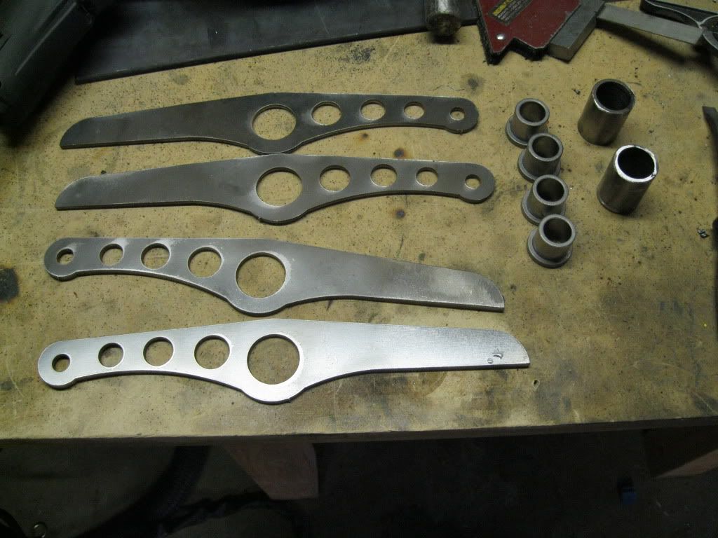
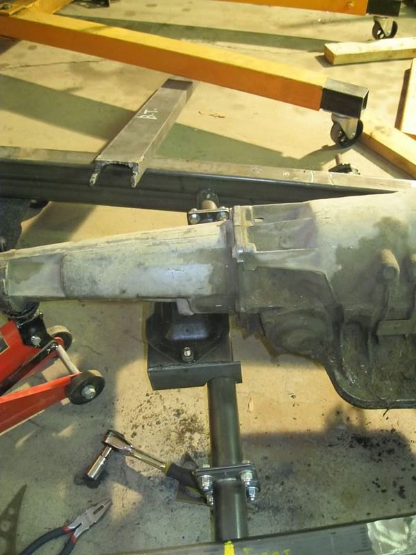
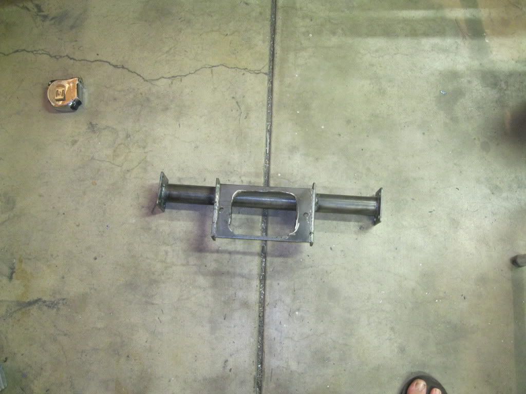
I added two brackets to the transmission mount plate. The brackets had half-circle cut-outs that allowed them to be welded to the tubular crossmember. I also made the center section of the cross member and bolted it in place. With the crossmember ready, I threw everything together.
IMG_0309.jpg


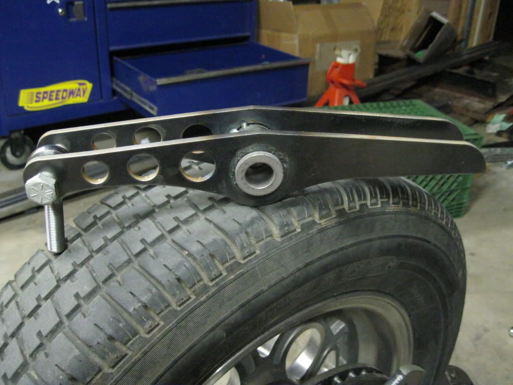
This is what the center section of the crossmember looks like. Yes, I wear flip flops when I weld and grind steel. It's freaking hot in AZ! :D
IMG_0311.jpg


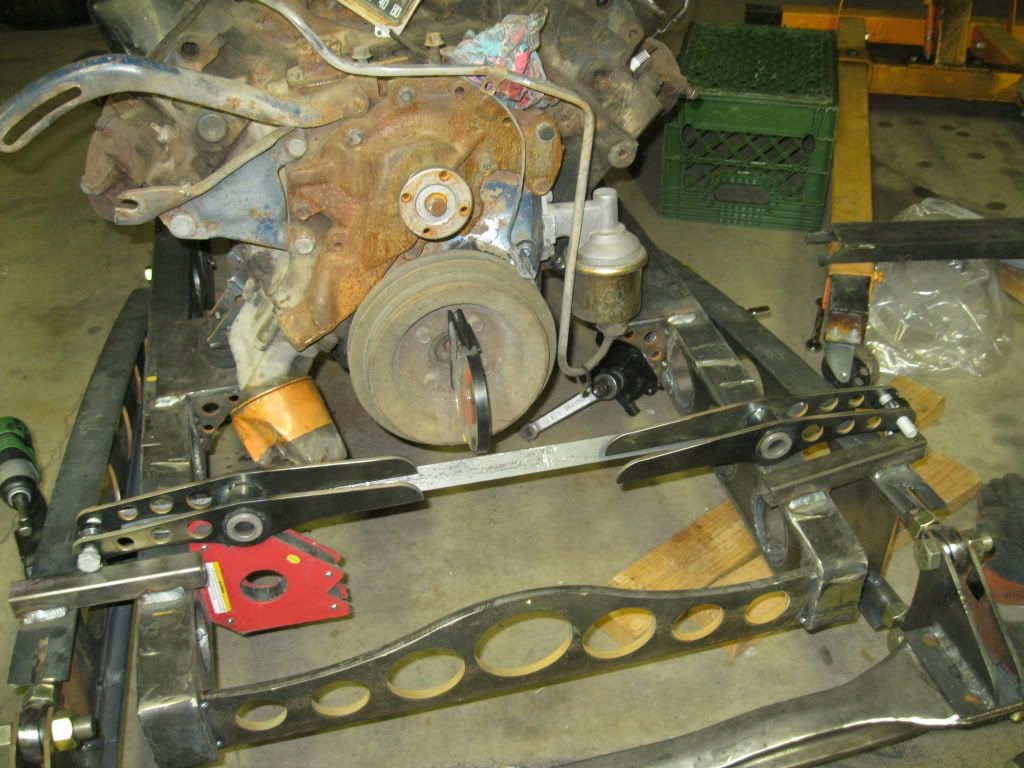
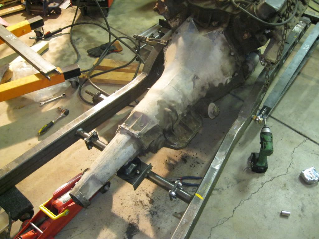
Here it is welded in place. I welded the crossmember such that the transmission angle with the transmission sitting directly on top of the cross member would be 3.5º. This allows me to shim the transmission to the final angle, and I can also drop the transmission 0.5º if I had to.
IMG_0312.jpg


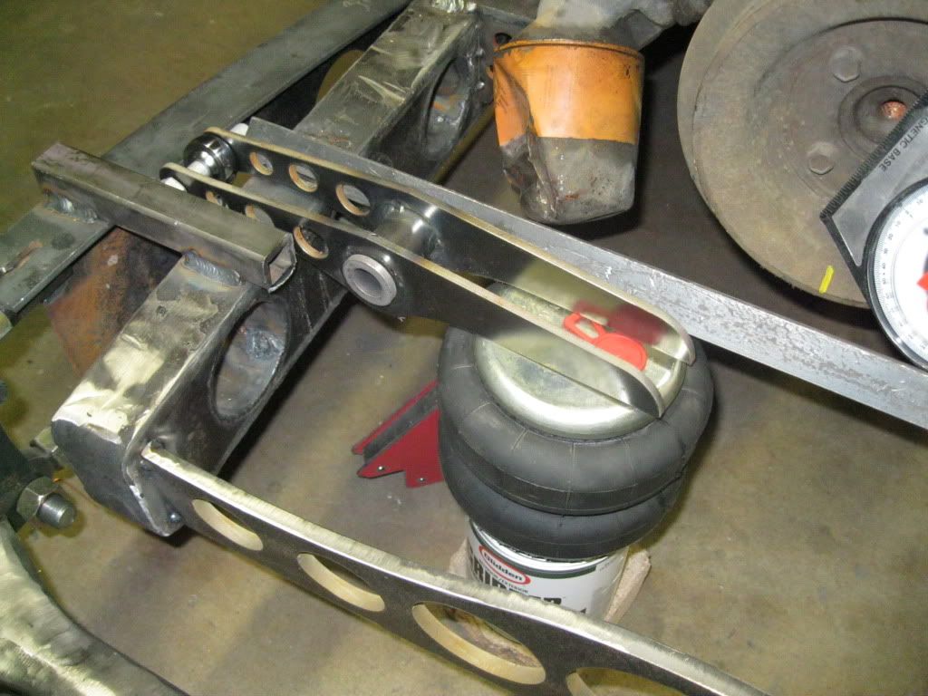
With this ou of the way, I can start on the front suspension. I'm so excited, I can't wait! :D

Thanks for looking! :)
 
Nice engineering on the tranny mount.

I was going to leave the Ackerman thing alone, but since you weighed in on it - Consider this: Fullsize 1500 (or C10) Chevy trucks vary the wheelbase from something like 118" for Blazer/Tahoe to 180" (rough estimates - I used to know the exact numbers) for the long bed 4 doors. But, the front suspension part numbers are the same for all wheelbases. This was true in 1978 and in 2000 and probably still is - they didn't make wheelbase length specific front suspension geometry. None one them are Ackerman correct.
 
I think it's called Ackerman approximate. I can tell you the Ackerman geometry on the 2008 regular cab short bed 1/2 ton GMC 4x4 I just got rid of probably wasn't even approximate. At full lock low speed turns the tires squealed like stuck pigs and hopped (bucked) all over the place.

Don't see how our back yard engineering can be much worse.

Amen to that, my 2008 F150 is no better.... Front steer solid axles are pretty common though, as I recall, my 75 Blazer was front steer and it didn't have that problem with tire scrub, even with 12.50 33"s on it. If you have the steering arms angled in something like the original arms for the Ford axle, it should be fine..
 
I think you will be very close as it sits. Your drag link pivots are outside the kingpin pivots. Most peoples front drag link set ups are the other way (pivots inside the king pin center line) which would make the outer wheel turn tighter than the inner (reverse from what you want). I think yours will be just fine.
 
[IMG said:
http://i33.photobucket.com/albums/d77/soroush1995/rat%20rod%20project/IMG_0302.jpg[/IMG]


Absolutely NOT TRUE! This will work well for really low speed turning, like horse wagons, for which Ackerman geometry was originally developed. Modern cars don't run a perfect Ackerman geometry and this is because dynamics effects, such as tire slip angle through turns, are not accounted for in the Ackerman geometry. The slip angle is a really important thing that a lot of people leave out of the equation when designing a steering system. A lot of high speed race cars (such as F1 cars) run reverse Ackerman because of slip angle.

I don't want this to sound harsh or rude. If it does, I apologize.

Nope were all good, Just something I have read..
 
This has been a fun and informative build thread to follow. Excellant photos and explanation.
Very well done MH.
402471.gif

Thanks Earthman! :)

Nice engineering on the tranny mount.

I was going to leave the Ackerman thing alone, but since you weighed in on it - Consider this: Fullsize 1500 (or C10) Chevy trucks vary the wheelbase from something like 118" for Blazer/Tahoe to 180" (rough estimates - I used to know the exact numbers) for the long bed 4 doors. But, the front suspension part numbers are the same for all wheelbases. This was true in 1978 and in 2000 and probably still is - they didn't make wheelbase length specific front suspension geometry. None one them are Ackerman correct.

Exactly!

I think you will be very close as it sits. Your drag link pivots are outside the kingpin pivots. Most peoples front drag link set ups are the other way (pivots inside the king pin center line) which would make the outer wheel turn tighter than the inner (reverse from what you want). I think yours will be just fine.

Yup, the whole idea is to make inside wheel turn tighter than the outside wheel. I'm not worried about the steering. It will steer fine.

------------------------

A quick update:

I've been really busy lately. I have accepted an engineering position with General Motors, for which I'm super excited. On the flip side of the coin, I have to wrap up all the projects I have at my current job before my last day, which is Friday Auguest/6. The new job requires quite a bit of travelling, which would unfortunately limit the amount of time I can spend on the rat rod, but I'm not complaining! :D

Anyways, I've started on the front suspension. I made the bell cranks for the airbag setup. I need to make a crossmember to hold the airbags, as well as some pushrods that are adjustable in length. I have some 1/2" heim joints that I will use, so all I'd have to do is make 2 turn buckles to connect the heims together.

These are all the parts that went into making the front bell cranks. There are 4 waterjetted arms, 2 pieces of DOM tubing and 4 flanged bronze bushings.
IMG_0315.jpg


Next step was to weld everything up:
IMG_0317.jpg


Here is one welded up:
IMG_0320.jpg


On the frame:
IMG_0319.jpg


Here you can kind of see how everything works once I make the crossmember and mounting points for the bell cranks.
IMG_0323.jpg


This is all for now. Time is becoming a pretty scarce thing around here. I need to get as much as I can before hell breaks loose. LOL!

Thanks for looking! :)
 
I like the design on the bell cranks - light, strong, easy to build and they look good.
I'm a huge believer in bronze bushings. They handle high loads very well, are self lubricating, easy to install and replace, have a built in thrust bearing, they never seize up and they're cheap.

Congrats on the job! Hopefully, it won't mean spending winters in Detroit and summers in Yuma.
 
Looking great! :D

Congratulations on the new job. [cl

Thanks!

I like the design on the bell cranks - light, strong, easy to build and they look good.
I'm a huge believer in bronze bushings. They handle high loads very well, are self lubricating, easy to install and replace, have a built in thrust bearing, they never seize up and they're cheap.

Congrats on the job! Hopefully, it won't mean spending winters in Detroit and summers in Yuma.

Bronze bushings are great! Another great thing about them is you can ream them to your desired size to have whatever clearance you want.

Haha, Yuma! A few years ago, I turned down a job with the army proving grounds in Yuma because it was in Yuma. That's a city that makes Albuquerque look like Paris. :D

Any progress updates?

There's no new progress unfortunately. :(

I had to go to Ohio/Indiana for my new job. I was out there for over a month and I just got back a few days ago. Unfortunately, I will fly back out there on Sunday. I'll be gone for another month or so. This seems to be the trend until December when this new program is kicked off and running. Until then, I will be working 10+ hour days, as there's a lot of design work that needs to be completed.

Since I'm on "vacation" until Sunday, I'll put a few hours in the rat rod. My plan is to get the front crossmember finished and tacked on. I would be happy if I could accomplish that much.

Thanks guys! :)
 
Motorhead - I just now looked through this entire thread for the first time. Really nice work - I like the way everything is turning out. I do have one concern I'd like to voice, though.

It may never be an issue - but I'm wondering if the steer arms mounted to the caliper brackets might cause you some braking issues, specially after parking lot manuevers that require high steering effort. What I'm visuallizing is the high steering efforts might very slightly flex the caliper mounts, causing the caliper to move a little bit relative to the rotor. When this happens the piston can retract just a little bit, opening up some slack in the system that equates to a long pedal before getting good brakes. Again - might not be an issue, but I've looked at a lot of spindles/brakes and never saw the steer arm loads put into the spindle via the caliper bracket.

Also - want to know why I thought about this? I have a Panoz Roadster that I built on my own while working for Panoz that has a similar issue on the rear brakes. When I started driving the car I noticed at random times that I had a really long brake pedal, to the point of having to pump them once to get a good pedal before stopping. It took a little while to figure it out, but the stiffness of the park brake cables puts very slight side loads into the calipers as the suspension travels.

Just wanted to bring it up in case you notice a random long brake pedal when you start driving it!
 
I'm back!! I thought I would never get back home. Only 19 days of the past 5 or so months have been spent at home. Living out of a suitcase for that long of a period truely sucks! On the bright side, we passed crash testing with flying colors. All my modules are done and have been handed down to production. I finally get to slow down for a little bit before the crap hits the fan again. I sure love the AZ weather. It's been in the low 70's lately. It was in the teens up in Michigan and Indiana when I left, really miserable! Anyways, it's nice to be back.

I haven't done much on the truck. My work space is a mess. I'm planning on cleaning it today and start working on the truck as soon as the shop is cleaned. I've finished designing the front crossmember and it's waiting to be water jetted. As soon as my water jetter gets back from the break, I'll get the ball rolling on that.

TubularFab - I've actually thought about the point you brought up, and it may very well become an issue. The caliper brackets seem really stiff and don't move at all when I pull/push on them. It's one of those things that will remain unknown until the truck is running. Thanks for bringing it up! :)

Anyways, I'm really pumped to get back to working on this truck. The weather is beautiful down here, so I should be able to make some decent progress quickly.

Thanks for looking! :)
 
Thanks guys! :)

It's been a long time since my last update with pictures. I really missed updating this thread, LOL. Anyways, here's a quick update:

I have all the parts to finish the front airbag system, with the exception of the pushrods and proper shocks. I borrowed two shocks from my buddy, none of which would work for me. I need to get something with about 7-8" of stroke.

Anyways, here are a couple of pictures of the front subframe. I'll weld it on the frame this weekend. I should have probably waited until the weekend for an update, but I couldn't wait! :D

My next update might even include a little video clip! ;)

Thanks for looking! :)

IMG_0693.jpg


IMG_0694.jpg
 
Neat set up. Do you really even need the shocks the way that is set up? Maybe I'm looking at it wrong, won't that give a really soft/smooth ride with the bags on the outboard side of the pivot?

Edit: I guess you still want to keep the wheels on the ground. So would the bags do OK on their own or is that asking for disaster?
 
Yes, shocks are still needed. The airbag only replaces the spring. You still need something top damp out the spring motion. It could be a fluid-filled shock, friction shock or even magnetic.

There's quite a few factors that determine the ride "smoothness". When it comes to the placement of an airbag or a spring, it is a function of the ratio of the lever arm to the moment arm. Think of it as a seesaw. The larger the lever arm is, the less force it takes to lift an object. The larger the ratio of lever to moment arm is on a suspension, the lower your spring rate (or airbag pressure) can be. If you use a bell crank (like my suspension), you can achieve a greater than 1:1 ratio, which would equal to a smoother ride. The down side is that you sacrifice suspension travel.

I hope it made sense! :)
 

Latest posts

Back
Top