DJ3100
Well-known member
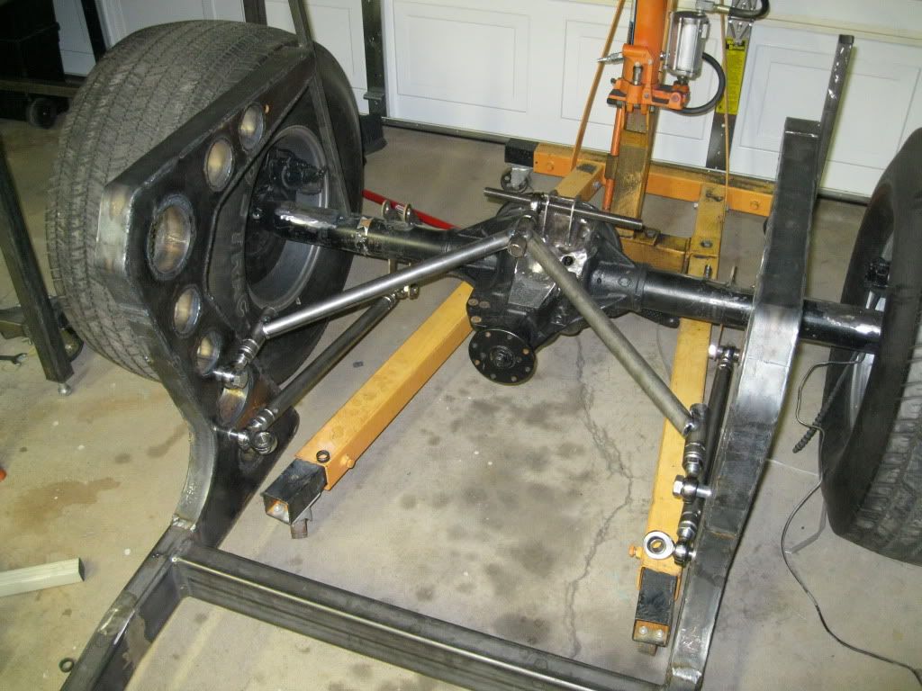
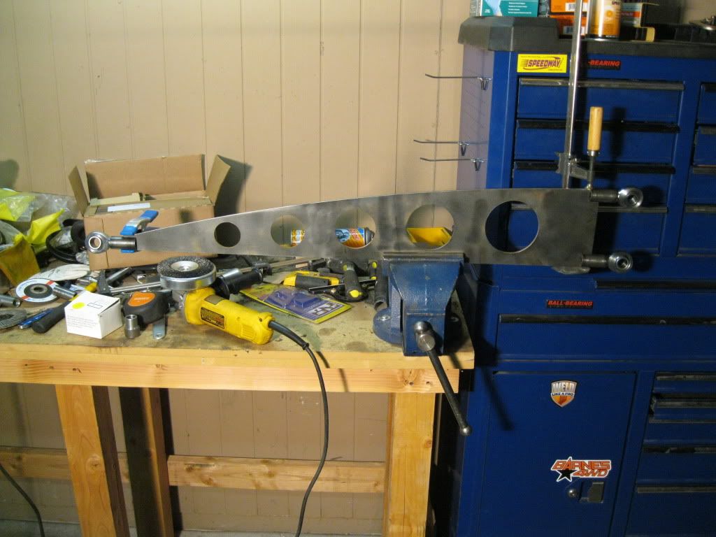
The frame is looking great!
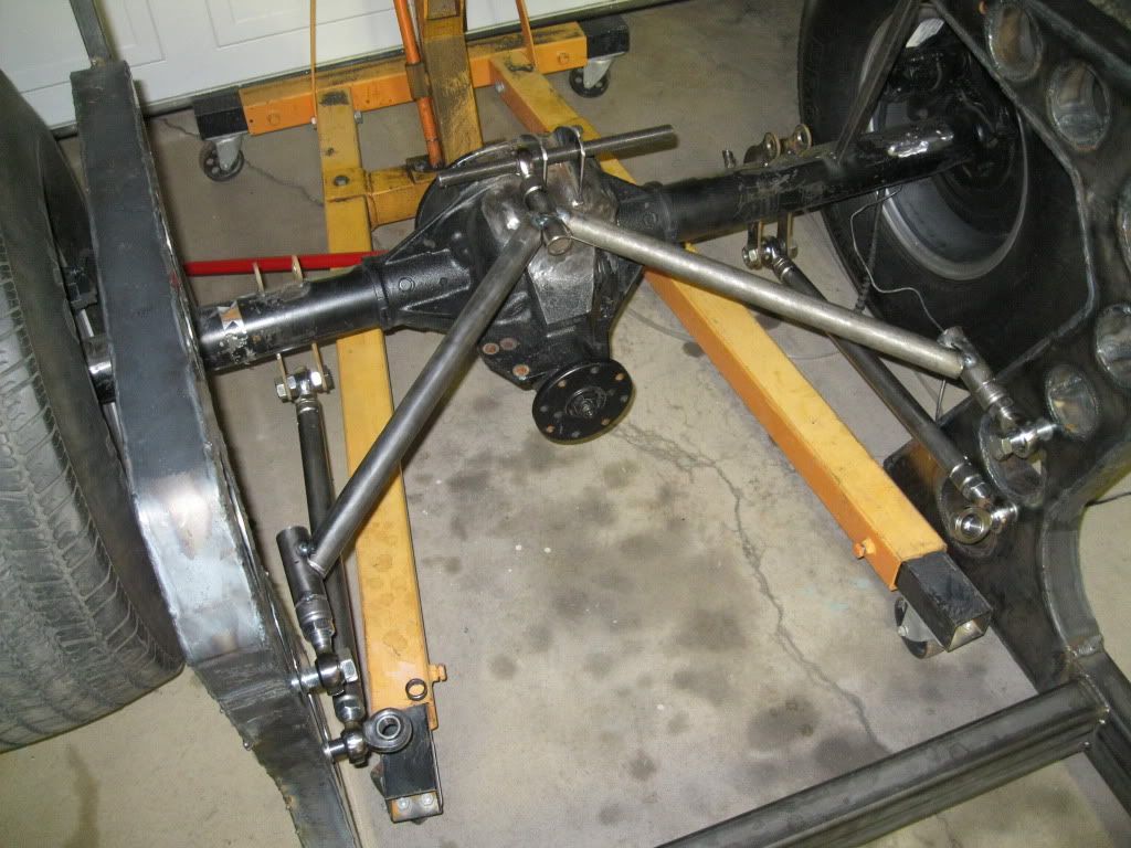
Does the distance of the links from the center line affect the "Tippiness" or is it just the spring/airbag distance from the center line? (I probably misunderstood the whole tippiness thing.) Anyhow, it looks better with the links inside the frame.
Does the distance of the links from the center line affect the "Tippiness" or is it just the spring/airbag distance from the center line? (I probably misunderstood the whole tippiness thing.) Anyhow, it looks better with the links inside the frame.

")