Stupid me! Stupid me! LOL
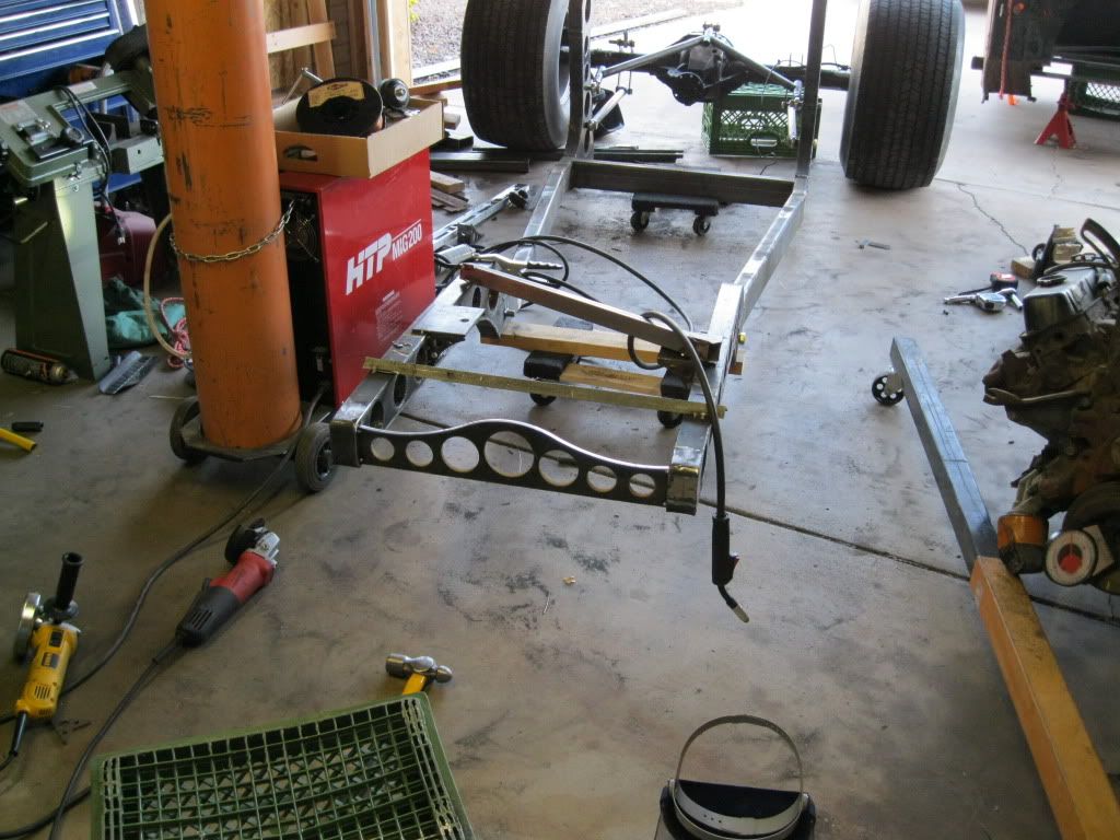
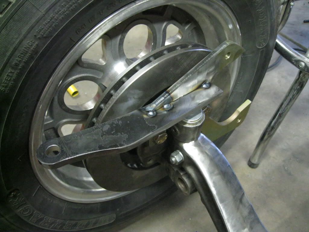
I realized this morning that the rearend was not centered on the frame. The actual pinion offset (according to the internet) is 2.1875", which yields about a 3.2º angle. I feel much better about this.
Thanks!
I don't know how they would work as body mounts. Theyre pretty big, probably 3" or so in diameter. I would just get a body mount kit from Auto Zone. It would probably come out cheaper in the end, as the Speedway mounts are $20 a pair.
For my body mounts, I ordered a 36" length of polyurethane tube from McMaster. It's 60A hardness and I'll cut pieces up to use as body mounts. It's 1/2" inside diameter with 3/8" wall thickness.
Thanks! It sure feels cooler today, a lot cooler! I'll get some more done, hopefully!
The pinion and output shaft are no parallel. Like I said earlier, the angle will be about 3º, so that makes life a lot easier. I think the U-joints can handle that, no?
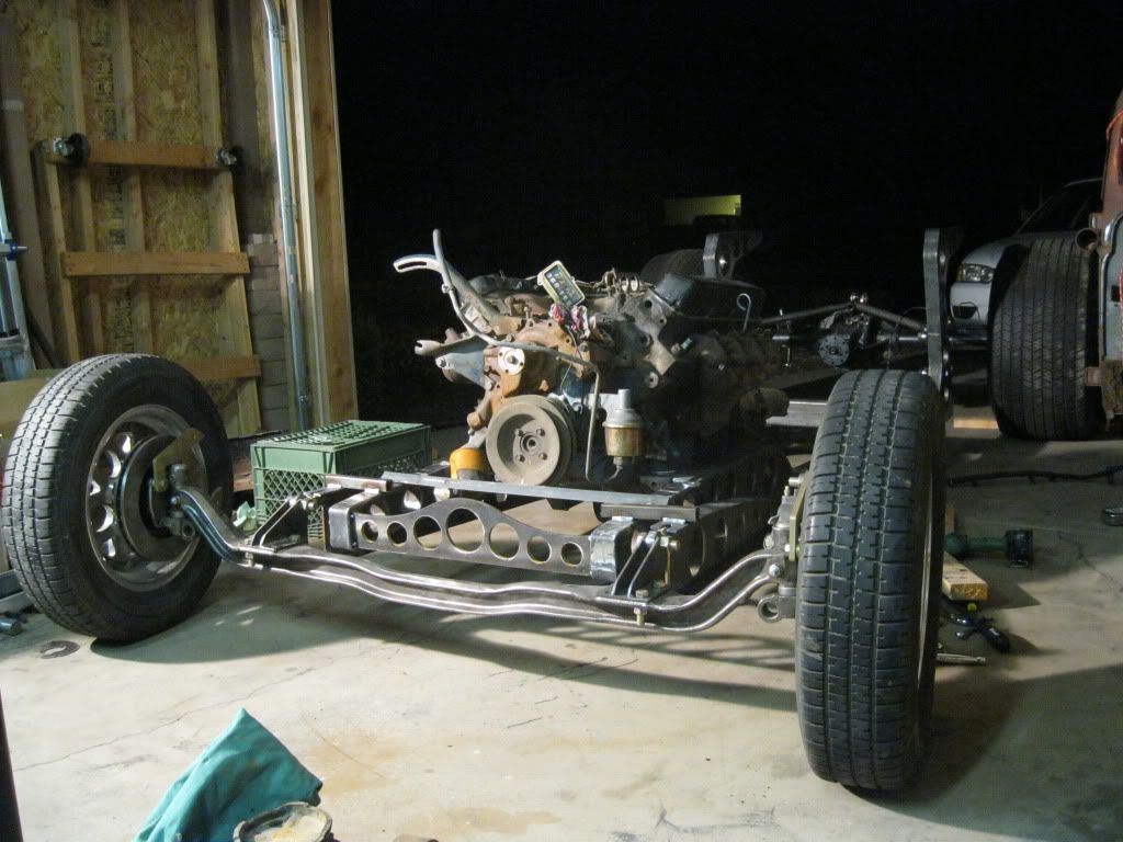
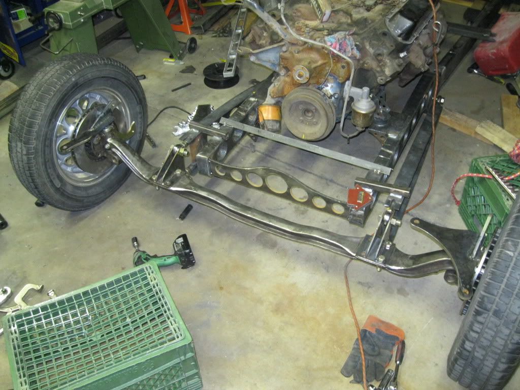
The pinion and output shaft are parallel in both planes:
Plane 1: the plane that runs the length of the car and is parallel to the ground.
Plane 2: the plane that runs the length of the car and is perpendicular to the ground.
Everything in plane 2 is perfect. I was worried about the driveshaft angle in plane 1. By mistake, I calculated it to be about 6.5º, but like I said earlier, it'll be more like 3º. I feel much better about that.
Thanks everyone!
I realized this morning that the rearend was not centered on the frame. The actual pinion offset (according to the internet) is 2.1875", which yields about a 3.2º angle. I feel much better about this.
looks good motorhead.
i was wondering being i never held one of them rubber motor mounts. do you think it would be a good body mount? i dont know the price differance from a poly but it was a thought. i just noticed yesterday after i put my masking tape drive shaft on that it had an offset, not as much as your though.
i really dont know the answer to your drive shaft. i hope it comes together for you. i thought i seen some one with a 6* drop in a universal before.
Thanks!
I don't know how they would work as body mounts. Theyre pretty big, probably 3" or so in diameter. I would just get a body mount kit from Auto Zone. It would probably come out cheaper in the end, as the Speedway mounts are $20 a pair.
For my body mounts, I ordered a 36" length of polyurethane tube from McMaster. It's 60A hardness and I'll cut pieces up to use as body mounts. It's 1/2" inside diameter with 3/8" wall thickness.
Are the pinion shaft and the output shaft parallel now? I think angling the tranny to take it out of parallel would not be the ideal solution. 6.5 degrees is more than the info I have recommends, but way less than the lifted trucks use. Hopefully someone who actually knows will come up with the correct answer.
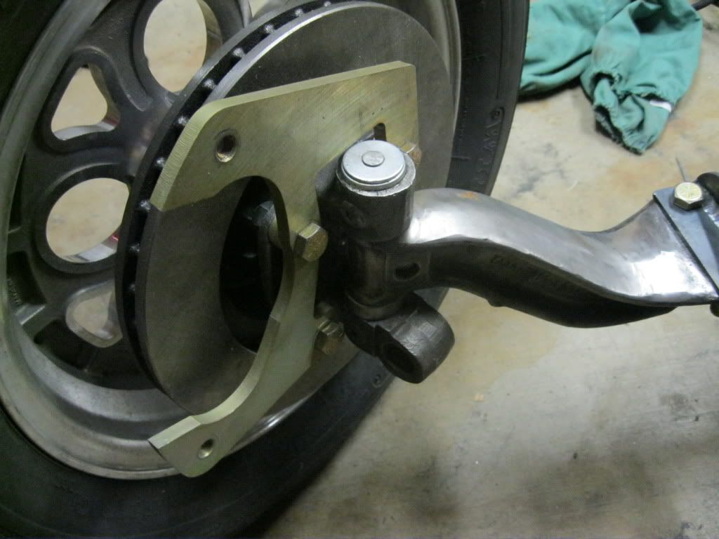
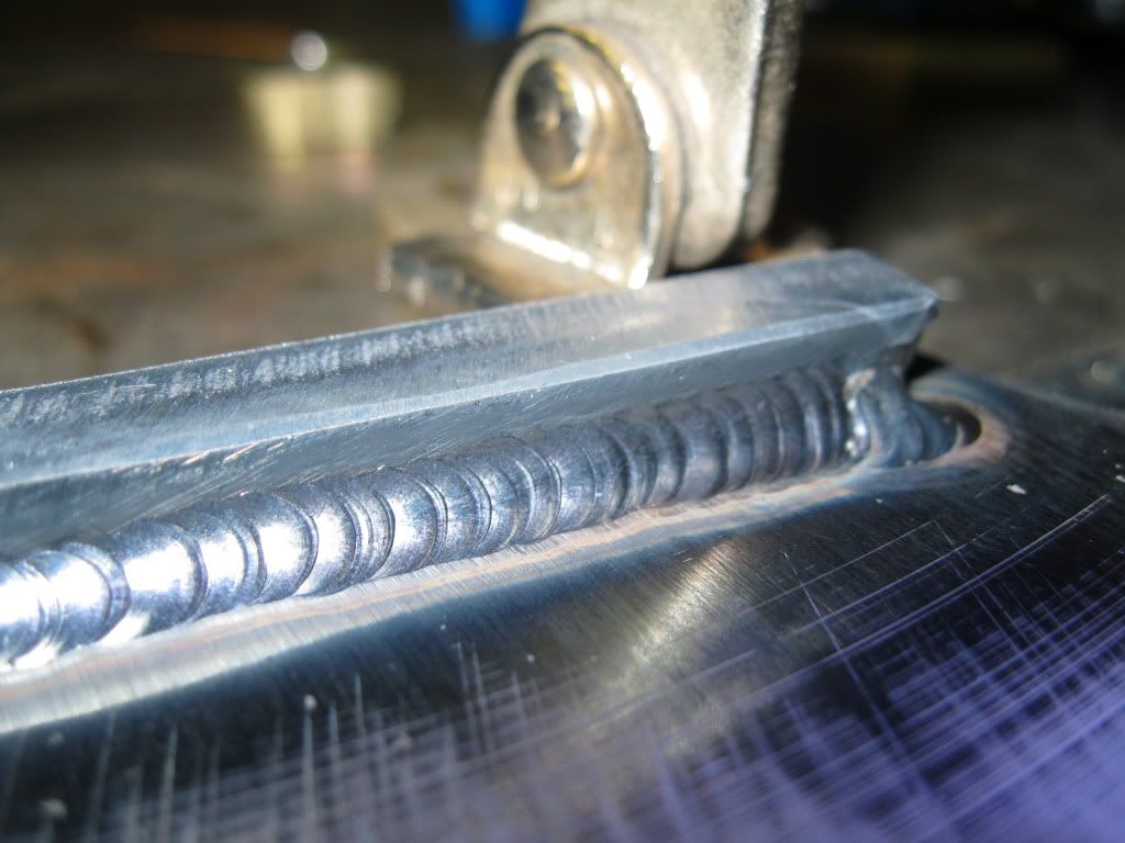
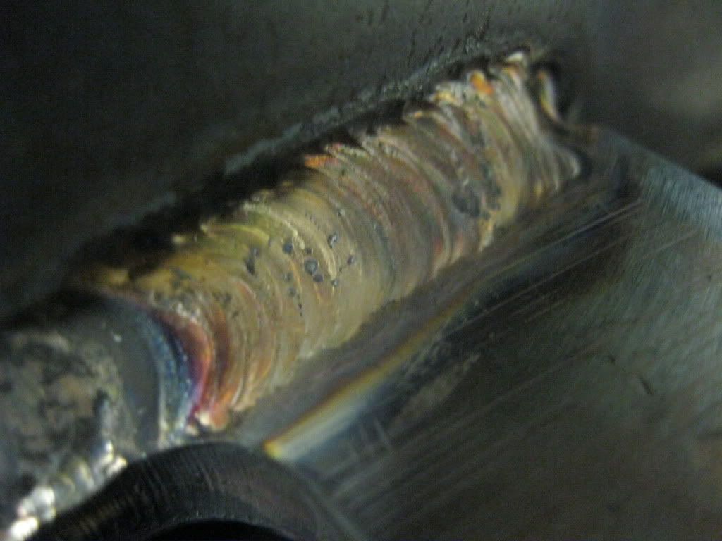
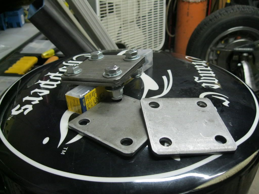
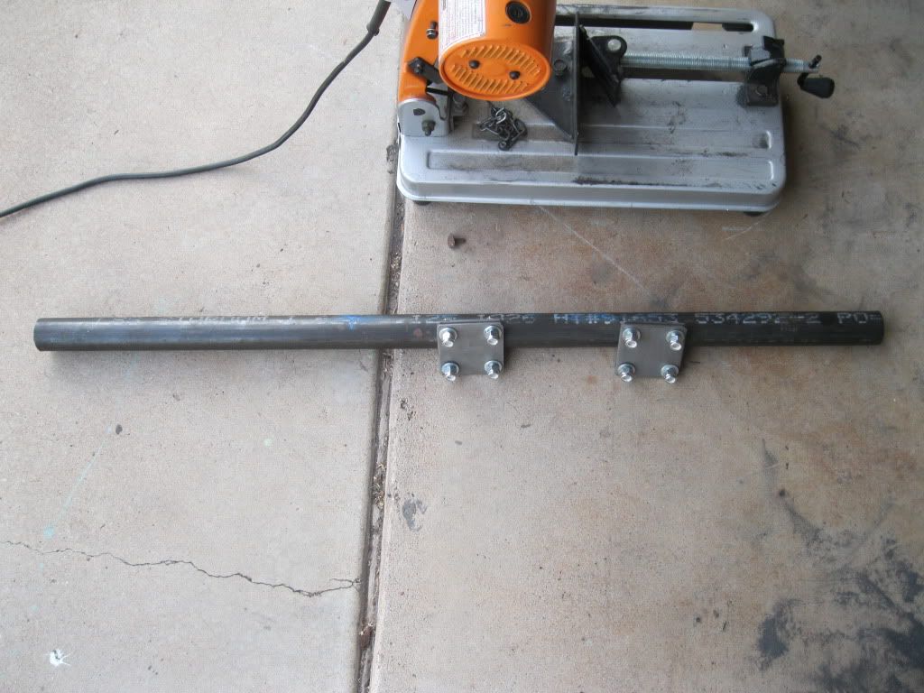
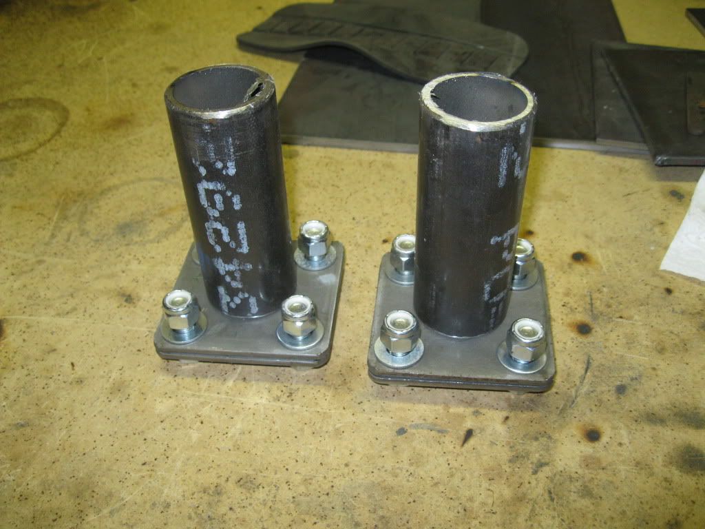
Motor mounts look great.
Cooler today - get lots done!
Thanks! It sure feels cooler today, a lot cooler! I'll get some more done, hopefully!
The pinion and output shaft are no parallel. Like I said earlier, the angle will be about 3º, so that makes life a lot easier. I think the U-joints can handle that, no?
The angle on the engine/trans and the angle on the pinion should be equal and opposite. An example: If the engine is angled down toward the rear at 3 degrees, then the pinion should be angled up 3 degrees. Because of elevation differences between the end of the tailshaft and the pinion, a maximum of 5 degrees in u-joint angle is ok.
Many people get by with more u-joint angle than that, however.
The pinion and output shaft are parallel in both planes:
Plane 1: the plane that runs the length of the car and is parallel to the ground.
Plane 2: the plane that runs the length of the car and is perpendicular to the ground.
Everything in plane 2 is perfect. I was worried about the driveshaft angle in plane 1. By mistake, I calculated it to be about 6.5º, but like I said earlier, it'll be more like 3º. I feel much better about that.
Thanks everyone!