Undead Sleds / Rat Rods Rule - Hot Rods, Rat Rods, Sleepers, Beaters & Bikes... since 2007!

Go Back   Undead Sleds / Rat Rods Rule - Hot Rods, Rat Rods, Sleepers, Beaters & Bikes... since 2007! > Transmission, Rear End... Talk & Q&A!

Transmission, Rear End... Talk & Q&A! Tranny, rear end, drivetrain related stuff... shift it... grind it... pop da clutch!

Reply
 
Thread Tools Display Modes
  #1  
Old 06-02-2014, 12:14 AM
NoShopSkills NoShopSkills is offline
Member
 
Join Date: May 2014
Posts: 32
Default Theoretical drive train geometry

Looking at the 3 and 4 link systems some have built in builds section leaves me perplexed.

I'm trying to understand how everything moves, but can't seem to learn the answers from reading build threads. Let's assume that I want to build a 4 link double triangulated, air bag rear axel system. Does it move straight up and down, perpendicular to the frame? Or does it follow a slight arc which is what it must do if the arms are solid, as it moves away from the frame? The rear end of the drive shaft has to follow an arc as it moves up and down, so unless the two are perfectly matched, the radius of each arc is slightly different.

In the same way that frame flex induces "bump steer", I'd think that the different radii between the usually longer drive shaft and comparatively shorter pivot arms, would cause the need for an expansion coupling, or at least splines that allow for some telescopic movement in and out between full compression and full expansion of the springs, to make up the difference... otherwise the drive shaft would be too short and sloppy, or too long and bound.

So when designing a suspension and drive train system, how do you compensate for the different arcs that are followed, one by the end of the drive train vs. the other, the end of the differential?
Reply With Quote
  #2  
Old 06-02-2014, 05:27 AM
RPM RPM is offline
The Rat Master!
 
Join Date: May 2007
Location: hills of TN
Posts: 1,067
Default

You are right about the driveshaft. That is why it has a slip yoke on the end that goes into the transmission. It lets the driveshaft be longer or shorter as needed.
__________________
Custom made CNC Plasma parts. www.eztbucket.com

Toll Free 855-TBUCKET
Reply With Quote
  #3  
Old 06-02-2014, 06:03 AM
donsrods's Avatar
donsrods donsrods is offline
Rusty Rat Rodder
 
Join Date: May 2007
Location: fort myers florida
Posts: 10,476
Default

You are overthinking it. RPM is right, just bolt it on and let the slip joint on the transmission compensate for any arc. Besides, rear ends don't move all that far anyway, unless the rear is bagged, and then you have to allow for a lot more movement in and out on the yoke. But overall, the movement is negligible.

Don
Reply With Quote
  #4  
Old 06-02-2014, 07:38 AM
Old Iron's Avatar
Old Iron Old Iron is offline
Rusty Rat Rodder
 
Join Date: May 2011
Location: Willard Mo.
Posts: 14,616
Default

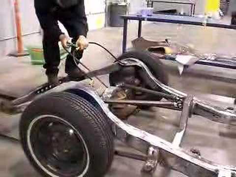
Watch this video to see how the rear end moves. It will answer 90% of your questions

http://shelf3d.com/Videos/7Z5awRcIkTU
Reply With Quote
  #5  
Old 06-02-2014, 08:18 AM
Sam_Fear's Avatar
Sam_Fear Sam_Fear is offline
Brother Rat
 
Join Date: Oct 2008
Location: Dixon, IA
Posts: 12,478
Default

There are some general "rules" that are followed when figuring drive train geometry. Trans/motor angle is usually 3 degrees down and pinion angle correspondingly is 3 degrees up. Tail shaft is 3/4" out from the transmission. Triangulated link angles and lengths are fairly standard too - but don't ask me what they are. If you need to use a panhard, the longer the better.
__________________
Not so current build - '29 A Rats-N-Rice. Drivers! - '48 Olds '63 F100. Pile of parts - '30 Tudor.
"Tough to find rolling papers that size, but it tastes like plastic bags and smells like arrogance!" -Dr. Crankenstein
Reply With Quote
  #6  
Old 06-02-2014, 08:35 AM
Old Iron's Avatar
Old Iron Old Iron is offline
Rusty Rat Rodder
 
Join Date: May 2011
Location: Willard Mo.
Posts: 14,616
Default

Here's an easy way to determine the amount of in and out movement of a drive shaft.
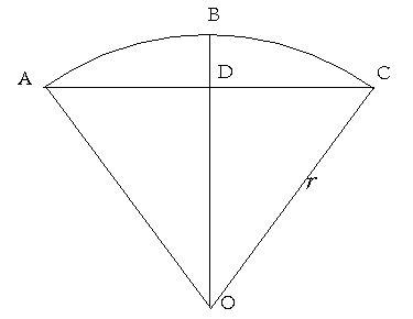
The first thing is to get something the length of the control arms you're using. I'll go with a yard stick.

Figure #1 is how to set it up


Figure #2 is axle arch length.
This is the maximum distance the axle will travel in it's up and down motion. Generally between 5" up 5" down (with airbags 10" up inflated and 10" down deflated).


Figure #3 is how to determine the distance the axle will move forward and back with the axle set in the center of it's up and down movement. (static ride height)
Measure the distance from point B to point D. This is that amount of forward movement.
Note: With a 4 link system, drive shafts do not move away from the tranny. The maximum distance away from the tranny is the starting position, points B


A triangulated 4 link system does not move side to side in it's up and down motion. It will move a very minimal distance in a heavy side load situation is all.
Hope this helps
Reply With Quote
  #7  
Old 06-02-2014, 08:43 AM
NoShopSkills NoShopSkills is offline
Member
 
Join Date: May 2014
Posts: 32
Default

Awesome thanks guys. Cool video. It helped me find a few links like this one!! Bit of a problem, because now I really like these cantilevered systems. Since I plan to build my own frame, I'll have to think through these too. This one is just incredible:

https://www.youtube.com/watch?v=ieXHZV-kcuw

It seems like these systems force the up and down movement to be more linear and less arcing too, so here a traditional slip yoke will allow for plenty of compensation. Maybe this discussion would have been a better fit under suspension, but I put it here because of the rear end driveshaft interplay.

In these more sophisticated scissor style systems you're asking for and getting a lot more from the airbags because of the leveraged forces involved. I'm days from buying a very heavy, hulk of an old car. Obviously there's a flood of vendors selling airbags. I'm only starting to open the pandora's box of understanding them, but I'm sure the load ratings and qualities are all over the map. Do builders typically source a specifically rated bag for each application or are they all in the same general ball park for automotive applications?
Reply With Quote
  #8  
Old 06-02-2014, 10:00 AM
NoShopSkills NoShopSkills is offline
Member
 
Join Date: May 2014
Posts: 32
Default

Thanks Old Iron! I had a similar plan in mind for comparing in/out travel. BTW, I took a look at your Pontiac thread. Very similar to the car I am considering. Haven't bought it yet, but it's in great condition compared to the other stuff I've been considering. I'll keep an eye on your progress and will let you know if I go for a Pontiac build.
Reply With Quote
  #9  
Old 06-02-2014, 11:07 AM
8literbeater's Avatar
8literbeater 8literbeater is offline
Rusty Rat Rodder
 
Join Date: Jun 2008
Location: Chandler, AZ
Posts: 849
Default

Quote:
Originally Posted by NoShopSkills View Post

https://www.youtube.com/watch?v=ieXHZV-kcuw

It seems like these systems force the up and down movement to be more linear and less arcing too, so here a traditional slip yoke will allow for plenty of compensation.
The shorter the arms, the more severe the arc is. The arms in that video are relatively short, so it's gonna need a well measured slip yoke to take up that travel. Also, since the arms are so short, the axle swings way forward, and there's no telling if it will clear the body panels. That particular setup in the video does horrendous things to the drive line angle. I would never run that on one of my vehicles, and I would never build that for someone.

My recommendation, for what it's worth, is to go with something simple. I don't want to be rude, but if you aren't familiar with driveshaft slip yokes, and U-joint angles, you might want to steer clear of three and four link air suspensions all together. You might be okay working with a universal kit. There might even be a kit that is meant for your car. Well, not if it's a '30s Pontiac.
For example: http://airbag-depot.com/catalog/avs-...77c8a38dbb791b

As far as the bag goes, generally, make sure the load rating is correct for the placement of the bag. One position can multiply the force on the airbag, another could divide the force on the airbag. If you have a 48" link, and you put the airbag in the middle of that link, the force on it will be double what it would be right on top of the axle. So 2000 pounds at the axle puts 4000 pounds on the airbag. Then after that, different bags have different rates, just like springs. Some people actually call them air springs. Generally, a big fat bag will have a higher rate, and will ride stiff. A small, thin bag will have a lower rate, and will be smoother, maybe too smooth, and you could be hitting the bump stops and the travel limiting straps just driving through an intersection. You won't like either one.
This is just about everything I know about air bag systems. I do know driveshafts, and angles, but not airbags so much.
Surely someone else can spread some more wisdom around here.
__________________

"The way to get started is to quit talking, and begin doing." -- Walt Disney

42 Chevy build

8literbeater build
Reply With Quote
Reply

Bookmarks

Thread Tools
Display Modes

Posting Rules
You may not post new threads
You may not post replies
You may not post attachments
You may not edit your posts

BB code is On
Smilies are On
[IMG] code is On
HTML code is Off


All times are GMT -5. The time now is 11:48 AM.


Powered by vBulletin® Version 3.8.8
Copyright ©2000 - 2023, vBulletin Solutions, Inc.
Rat Rods Rule Inc.