29 ford ls1

Rat Rods Rule

Help Support Rat Rods Rule:

This site may earn a commission from merchant affiliate links, including eBay, Amazon, and others.

TUCK3R

Member
Joined
Nov 14, 2014
Messages
10
Location
australia
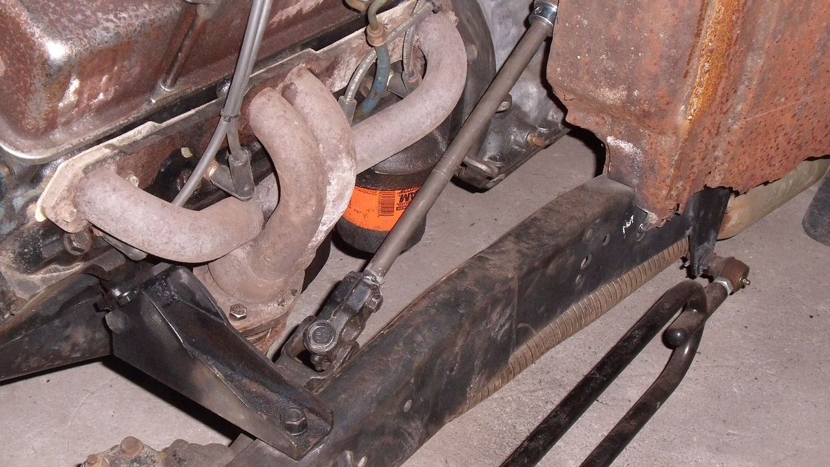
hey everyone i have a 29 ford a bit of a side project that we are putting together. It has a 5.7l motor and 4 speed . block huggers to clear steering.

What my question is steering coupling to rack and pinion steering to the colum. How have people done this? Is there a generic kit you can buy and adapt to your specific application or do you just make it out of wrecked cars /donor vehicles. The way i have to do it is gouverned by an engineer as it needs to be engineered to be passed for road use in australia. The main stipulation is 10 mm clearnace around steering and it needs to have a steering idler on the chasis. Any advice would be appreciated.

51684331db7ae2785f4f9133b7349e64.jpg

Thanks
 
I almost went on a 'get an engineers opinion' rant. While you and I were out in the back building things, some rich guys son was sent to university to get his degree. He can't build an inclined plane out of a one axled skate board, but he has a card saying he's always right.
Sorry, I guess I ranted.
It's not your fault that your have to get an engineers nod.
Here is my steering shaft picture. The chunk between the box and the column is out of a '91 Ford 150 pick-up. The column and the box are from an '87 Ford Ranger. There is a U-joint, a rag joint and a telescoping slide in that piece. It looks like you will have to go out around your exhaust so you will need another U-joint and Heim joint steady bearing.
Good luck and keep on tinkering.
 

Attachments

  • IMG_1297.jpg
    IMG_1297.jpg
    124.5 KB · Views: 28
I almost went on a 'get an engineers opinion' rant. While you and I were out in the back building things, some rich guys son was sent to university to get his degree. He can't build an inclined plane out of a one axled skate board, but he has a card saying he's always right.
Sorry, I guess I ranted.
It's not your fault that your have to get an engineers nod.
Here is my steering shaft picture. The chunk between the box and the column is out of a '91 Ford 150 pick-up. The column and the box are from an '87 Ford Ranger. There is a U-joint, a rag joint and a telescoping slide in that piece. It looks like you will have to go out around your exhaust so you will need another U-joint and Heim joint steady bearing.
Good luck and keep on tinkering.

Thanks for advice, engineer is a pain and cost $300 a go . I had a look at the speedway speed shop and there is everything there needed to make a system, just getting something that works well and no binding is the main issue.
 
Since you're from down under I see you're on the opposite side from us but that makes no diff. The angle of your steering column is a lil severe but 1st I'd put u-joints on both ends then measure the distance in between & order a shaft to fit. Can't remember what the largest angle for a u-joint is but surely one of the parts houses can tell you. Should be pretty easy unless you need a 3rd u-joint to quell those angles to prevent binding. I'm sure someone can post an example! Looks like you have splined ends on the column & the rack so you can either use splined or switch to double-d for the shaft! Also, I usually use a damper u-joint on the column to cut down on road vibration.

A double U might even be the ticket for those angles. Something like this,

http://www.speedwaymotors.com/Garage-Sale-Sweet-Mfg-Chrome-Double-Steering-U-Joint-Ididit-Column-to-Pinto-Manual,93577.html

Beercan
 
Last edited:
There are u-joints available that weld on the shaft and you can use a generic shaft and cut to length to fit any way you want. Mine was simple with one joint, but I'm not held to the rules you are.
 
Here's how I navigated limited space around the BB Nailhead in my truck to a R&P front steering unit. I used 3 u-joints & there's no binding & steering is awesome!!! Splined on both ends & DD in the middle sections. I cut the DD sections to length from a single piece.

BoB
 

Attachments

  • ujoints.jpg
    ujoints.jpg
    107.4 KB · Views: 23
Thanks for all the input everyone. its given me alot to think about and a direction i can go with the rod now. A few people have told me im pushing sh#t up hill with my header setup as it makes the steering shaft have to many unis to be able to work without being notchy. I will see how this all goes.

Dan

Dan,
Don't over think it, it's not rocket science. IMO you'll need a 3 u-joint setup and that should do it to the engineers satisfaction if you use sturdy u-joints. You'll be able to do it no sweat! Good luck!

Toad
 
Here's a couple more versions of the same thing, typical aftermarket u-joints (Borgeson and Speedway) and 3/4"DD shafting, 3/4" heim joint used as the steady bearing. In your case, you may need to modify 1 or more pipes of the header to get the shaft and joints past it.
 

Attachments

  • aug 31 11 34 cadillac 001.jpg
    aug 31 11 34 cadillac 001.jpg
    101.4 KB · Views: 17
  • DSC02089.jpg
    DSC02089.jpg
    102.2 KB · Views: 16
Dan,
Don't over think it, it's not rocket science. IMO you'll need a 3 u-joint setup and that should do it to the engineers satisfaction if you use sturdy u-joints. You'll be able to do it no sweat! Good luck!

Toad


Yeh i think your right, its just i want to build something that is safe.Just a bit unsure as its my first attempt at making steering linkages.With everyones advice on this forum i have enough information to do the job safetly.
 
Here's a couple more versions of the same thing, typical aftermarket u-joints (Borgeson and Speedway) and 3/4"DD shafting, 3/4" heim joint used as the steady bearing. In your case, you may need to modify 1 or more pipes of the header to get the shaft and joints past it.


Thanks Mate
 
Sorry it took so long for me to get back here.
Tuck, If you use the 3/4" double D shaft that is machined it's entire length, the 3/4" double D u-joints will automatically be clocked correctly.
ujointtypes.gif


31tdATRUO1L._SL500_AA300_.jpg


These double joints are great for tight angles
9109120_L.jpg

Thanks for the infor mate it is much apprieciated.
 

Latest posts

Back
Top