donsrods
Well-known member
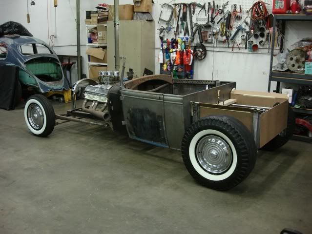
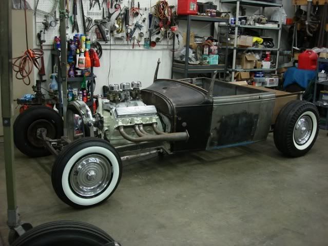
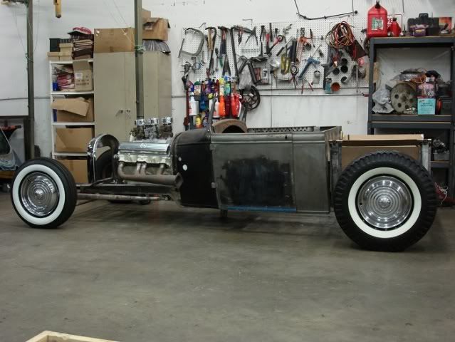
Thank you, Preacher. ") I spent tonight doing more mockups on the car to see how certain things would look. I had a masonite bed that I had built as a test and I put it on to see how it would look. Then I lowered the car down in the back to where it will ultimately ride, and I put on the 1956 Olds hubcaps so that I could determine if I was going to run them or not. After seeing them on the car I think I will keep them, it needs some shiny stuff on it and I have always liked hubcaps on hot rods.
I spent tonight doing more mockups on the car to see how certain things would look. I had a masonite bed that I had built as a test and I put it on to see how it would look. Then I lowered the car down in the back to where it will ultimately ride, and I put on the 1956 Olds hubcaps so that I could determine if I was going to run them or not. After seeing them on the car I think I will keep them, it needs some shiny stuff on it and I have always liked hubcaps on hot rods.
So here are some pictures when I got all that done.
Don
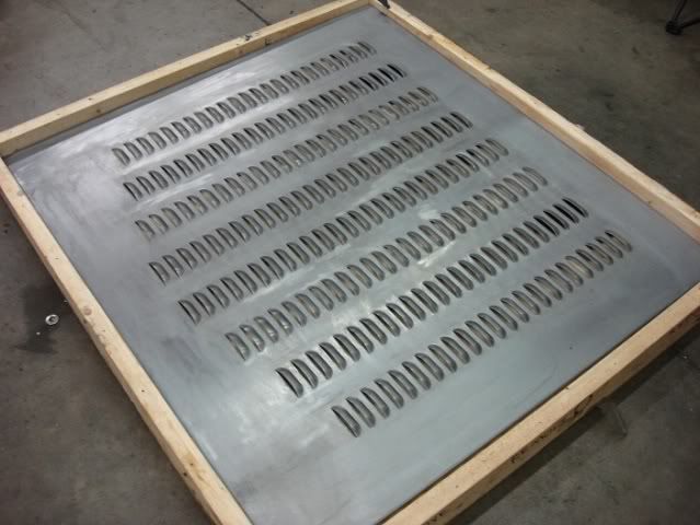
About 5 years ago we packed away the tonneau cover my Son Dan was going to use on his rpu, but that he never used. Tonight I opened up the crate and it looks like I will be able to cut it up and use it as a bed cover on my car to hide all the suspension in the rear. It is punched with 224 louvers, so it would be a shame not to use it.
I spent tonight doing more mockups on the car to see how certain things would look. I had a masonite bed that I had built as a test and I put it on to see how it would look. Then I lowered the car down in the back to where it will ultimately ride, and I put on the 1956 Olds hubcaps so that I could determine if I was going to run them or not. After seeing them on the car I think I will keep them, it needs some shiny stuff on it and I have always liked hubcaps on hot rods.So here are some pictures when I got all that done.
Don
About 5 years ago we packed away the tonneau cover my Son Dan was going to use on his rpu, but that he never used. Tonight I opened up the crate and it looks like I will be able to cut it up and use it as a bed cover on my car to hide all the suspension in the rear. It is punched with 224 louvers, so it would be a shame not to use it.
Last edited: